TeqBlog
Localized movement sensing for SAR applications
Localized movement sensing limits the amount of radiation to the human body by detecting whether a mobile device is placed on a stationary object or is in use by a human. Capacitive proximity sensor technology offers increased performance by differentiating between typical human use and stationary materials – whilst complying with FCC SAR standards.

Posted by Riaan du Toit | 10 July 2019
Introduction
Specific absorption rate (SAR) is the measure of the rate at which energy is absorbed by the human body when exposed to the radio frequency (RF) electromagnetic field (EMF) of an electronic device. The Federal Communications Commission (FCC) has strict limits regarding safe SAR levels in mobile devices such as smartphones and tablets. This tends to force manufacturers to sacrifice performance for safety. Localized movement sensing limits the amount of radiation to the human body by detecting whether the mobile device is placed on a stationary object or in use by a human. Capacitive proximity sensor (P-sensor) technology offers increased performance by differentiating between typical human use and stationary materials (e.g. placement on a table) – whilst complying with FCC SAR standards.
SAR Proximity sensor application
P-sensors are favored for limiting SAR because of the omnidirectional nature of their E-fields, which effectively cover the area around the RF antenna. When a mobile device is used near a human body, the sensor is triggered in order to reduce the RF output to an acceptable level.
P-Sensor challenges
P-sensors are subject to unique challenges related to the sensor core technology. These are listed below:
- P-sensors rely on detecting changes in the E-field. Any type of material/object can cause change in an E-field, although only detection of the human body is required in this case.
- Materials used for “transporting” the sensing signal to the area of interest are known to cause capacitive changes (dielectric property changes) with changes in temperature and humidity. Polyimide, FR4 and coax cables are all known to cause significant capacitance changes with changes in temperature and humidity. Capacitance changes are also dependent on the design, and are more noteworthy than capacitance changes related to proximity sensing.
- On-chip sensor “engine” hardware is normally influenced by temperature. The degree of influence depends on the chosen P-sensor.
Solution
Normal proximity detection is dependent on the environmental and material state at the time of crossing the proximity threshold. During the time of proximity-based “activation”, it is complex and more costly to compensate for the environmental and material state. Localized movement sensing is a solution that addresses all of these challenges through the detection of human behavior, rather than stationary objects and slow-changing environmental effects, to finally increase sensing performance.
Introducing localized movement sensing
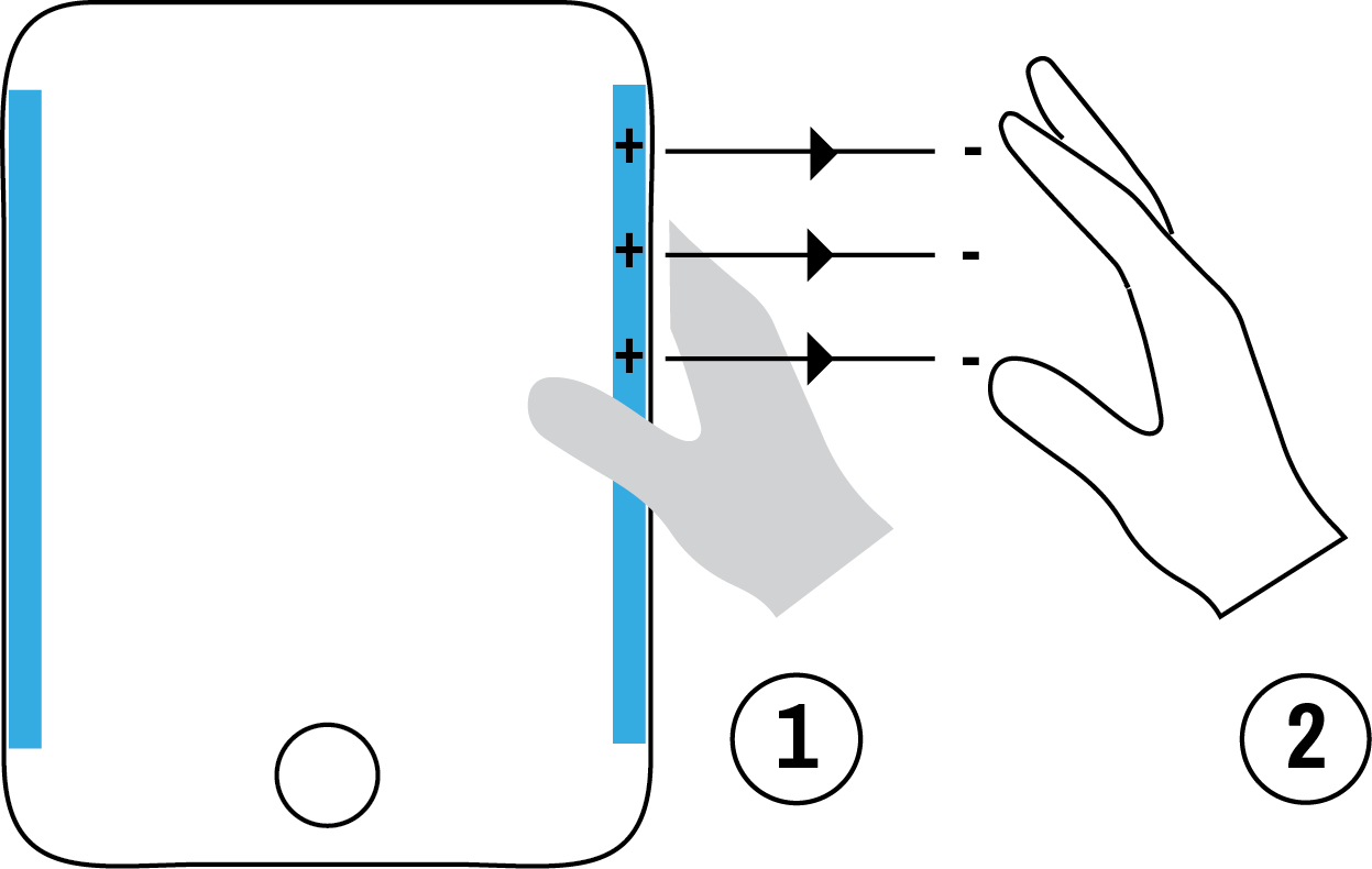
Movement sensing is generally understood to rely on accelerometer (‘G-sensor’) data and can only sense the movement of the device unit as in Figure 1. Localized movement sensing senses the movement between the unit and another object (e.g. a human or a table), as in Figure 2. The sensing is done around a confined area of the unit and movement cannot be sensed without another object being close to the confined area.
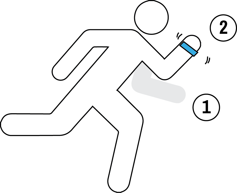

Figure 1: Unit movement sensing
Figure 2: Localized movement sensing
Typical movement-sensing capabilities
A test setup is used to demonstrate the typical sensing capability of a localized movement sensor. The device under test (DUT), as seen in Figure 3, consists of a P-sensor IC (IQS231A) with integrated movement-sensing algorithm, two P-sensor pads and an earth (GND) connection. The DUT is placed on a moving platform at variable separation distances from a stationary copper phantom body (Figure 4). Conductive copper is considered a close equal to the effect of a human body on capacitive sensing. The phantom body is connected to the same earth as the sensor IC. The DUT is connected to a computer to capture data through the Azoteq CT210A device.
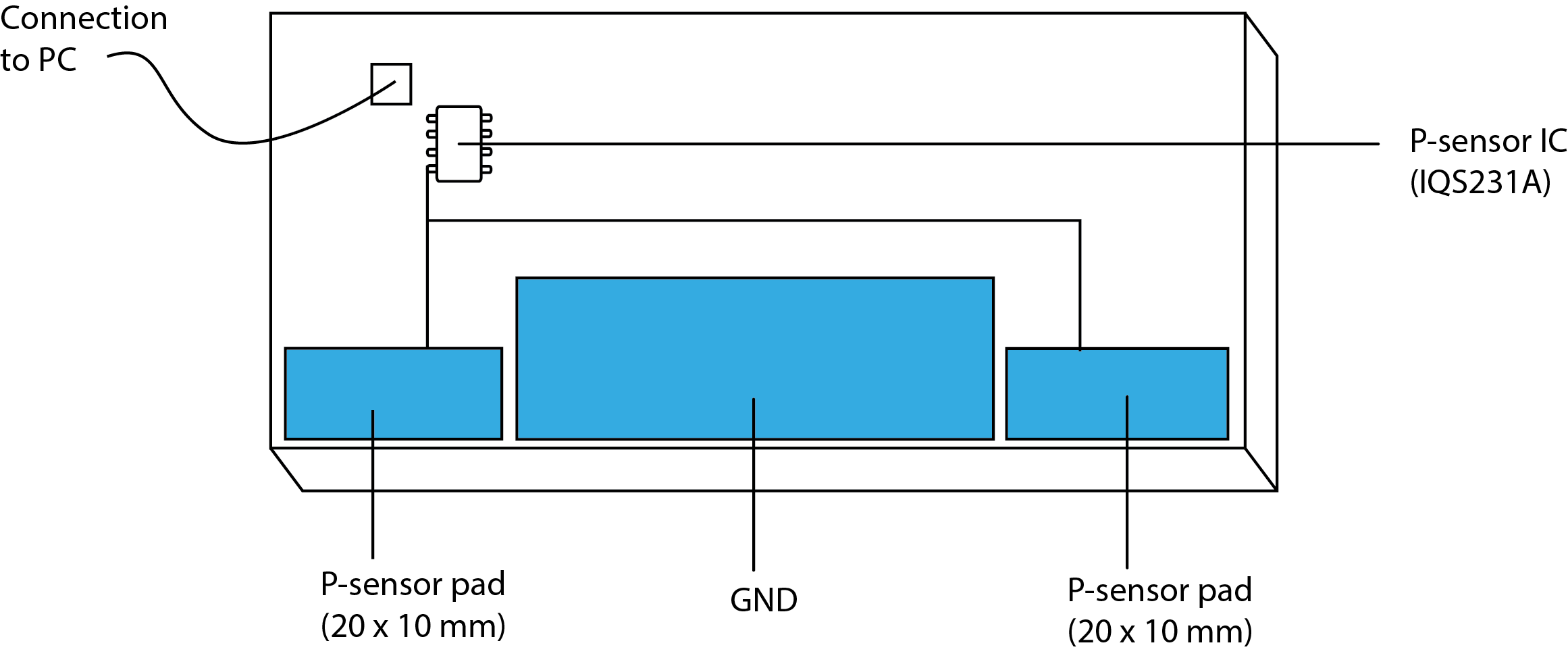
Figure 3: DUT example pad layout
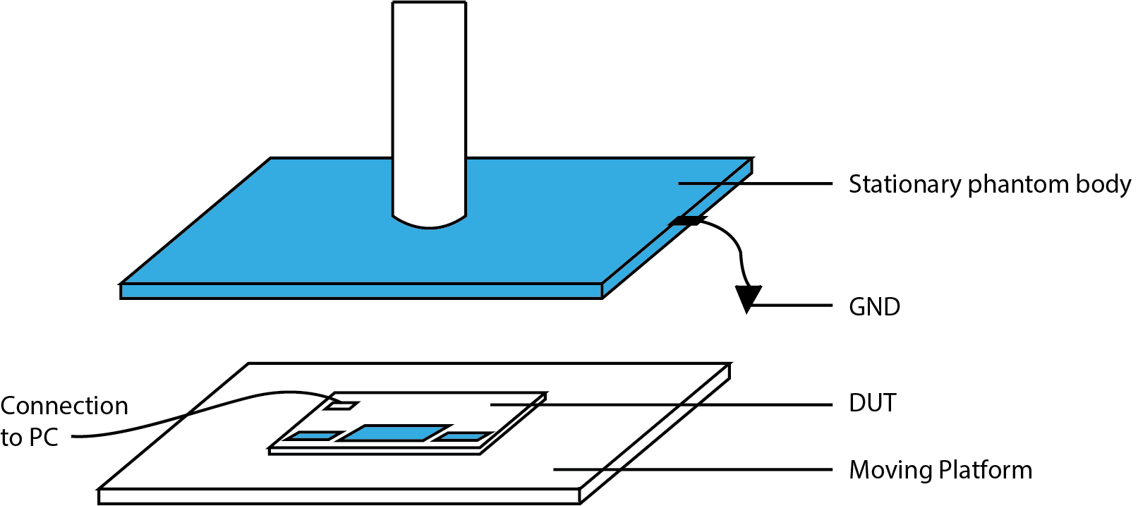
Figure 4: Movement sensing test setup
At every separation distance, the DUT is moved x mm closer and x mm farther from the phantom body (0.01 mm resolution) in order to determine the minimum movement distance required to trigger a movement event. Figure 5 distinguishes between separation distance and movement distance.
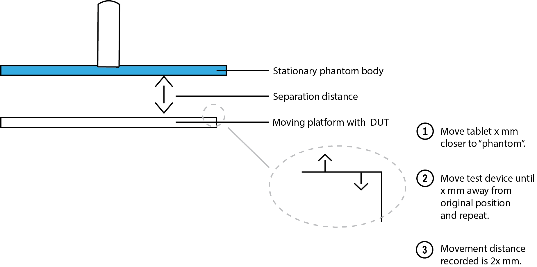
Figure 5: Separation distance compared to movement distance
Results
The results show the expected increase in movement sensitivity closer to the sense pad. With the DUT against the phantom, movement of the device by is able to trigger a movement event. The results in Table 1 indicate the extreme sensitivities close to the device. This clearly shows the safety and performance of the technique for limiting SAR exposure from mobile devices.
| Test Number | Separation distance | Movement trigger distance (mm) |
|---|---|---|
| 1 | 15 mm | 0.8 |
| 2 | 10 mm | 0.45 |
| 3 | 5 mm | 0.13 |
| 4 | 0 mm | 0.01 |
Movement sensing and FCC
Localized movement detection has been implemented to trigger power reduction based on a specific chipset, in conjunction with proximity sensing and by using specific parameter settings.3 The implementation is reviewed on the basis of clear FCC pre-approval guidance (PAG). Guidance on the approval procedure is available from Azoteq on special request.
Conclusion
Manufacturers tend to settle for lower sensing performance in order to comply with SAR regulations. Localized movement sensing with capacitive P-sensors offers:
- Extreme movement sensitivity
- Additional information on user presence, absence and behavior
- Low power consumption (typical of capacitive-sensing technology)
- Improved RF performance
- Safety as a priority
- Solid solution for the drift issues to which P-sensors are typically exposed
The technique discussed in this article is typically implemented in an ASIC, where the movement sensing is integrated with the proximity sensing. Applications include proximity backlighting for TV remotes, play-detect for toys, and SAR for mobile phones, laptops, tablets, mobile routers and Wi-Fi routers. For more information on the topic, please contact the author.
About the author
Riaan du Toit is an application engineer with seven years’ experience in various specialty proximity-sensing applications, including SAR, wear detect and on-ear detection. He holds an M.Sc. degree in electronic engineering and currently works at the Azoteq R&D Headquarters in South Africa. Riaan can be reached at [email protected]
References
- Sun, J; Hynynen, K (1998). “Focusing of therapeutic ultrasound through a human skull: A numerical study”. Journal of the Acoustical Society of America 104 (3 Pt 1): 1705–15.
- Federal Communications Commission. (2018). Specific Absorption Rate (SAR) for Cellular Telephones [online]. Available at: https://www.fcc.gov/general/specific-absorption-rate-sar-cellular-telephones [24 July 2018].
- FCCID.io. (2018). EM7455D2 LTE Module RF Exposure Info Test Report RFExp. Fujitsu Limited [online]. Available at: https://fccid.io/EJE-EM7455D2/RF-Exposure-Info/Test-Report-RFExp-3734053 [24 July 2018].
